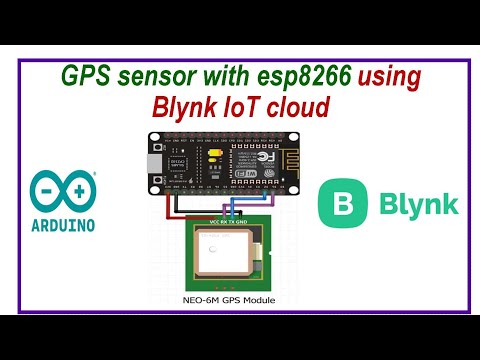
Circuit Diagram

#include "LedControl.h"
#include "binary.h"
/*
DIN connects to pin 12
CLK connects to pin 11
CS connects to pin 10
*/
LedControl lc=LedControl(12,11,10,1);
// delay time between faces
unsigned long delaytime=1000;
// happy face
byte hf[8]= {B00111100,B01000010,B10100101,B10000001,B10100101,B10011001,B01000010,B00111100};
// neutral face
byte nf[8]={B00111100, B01000010,B10100101,B10000001,B10111101,B10000001,B01000010,B00111100};
// sad face
byte sf[8]= {B00111100,B01000010,B10100101,B10000001,B10011001,B10100101,B01000010,B00111100};
void setup() {
lc.shutdown(0,false);
// Set brightness to a medium value
lc.setIntensity(0,8);
// Clear the display
lc.clearDisplay(0);
}
void drawFaces(){
// Display sad face
lc.setRow(0,0,sf[0]);
lc.setRow(0,1,sf[1]);
lc.setRow(0,2,sf[2]);
lc.setRow(0,3,sf[3]);
lc.setRow(0,4,sf[4]);
lc.setRow(0,5,sf[5]);
lc.setRow(0,6,sf[6]);
lc.setRow(0,7,sf[7]);
delay(delaytime);
// Display neutral face
lc.setRow(0,0,nf[0]);
lc.setRow(0,1,nf[1]);
lc.setRow(0,2,nf[2]);
lc.setRow(0,3,nf[3]);
lc.setRow(0,4,nf[4]);
lc.setRow(0,5,nf[5]);
lc.setRow(0,6,nf[6]);
lc.setRow(0,7,nf[7]);
delay(delaytime);
// Display happy face
lc.setRow(0,0,hf[0]);
lc.setRow(0,1,hf[1]);
lc.setRow(0,2,hf[2]);
lc.setRow(0,3,hf[3]);
lc.setRow(0,4,hf[4]);
lc.setRow(0,5,hf[5]);
lc.setRow(0,6,hf[6]);
lc.setRow(0,7,hf[7]);
delay(delaytime);
}
void loop(){
drawFaces();
}


No comments:
Post a Comment