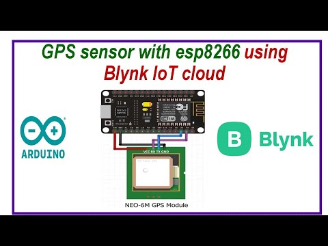
Monday, October 31, 2022

Internet based Digital Clock using esp8266 and OLED display


Circuit Diagram


Program Code:

#include <ESP8266WiFi.h>

#include <time.h>


#include <SPI.h>

#include <Wire.h>

#include <Adafruit_GFX.h>

#include <Adafruit_SSD1306.h>


#define OLED_RESET LED_BUILTIN //4

Adafruit_SSD1306 display(OLED_RESET);


const char* ssid = "******";

const char* password = "*******";


int ledPin = 13;


int timezone = 5.5 * 3600;

int dst = 0;


#define SSD1306_LCDHEIGHT 64

#if (SSD1306_LCDHEIGHT != 64)

#error("Height incorrect, please fix Adafruit_SSD1306.h!");

#endif


void setup() {


display.begin(SSD1306_SWITCHCAPVCC, 0x3C);


// Clear the buffer.

display.clearDisplay();

display.display();


pinMode(ledPin,OUTPUT);

digitalWrite(ledPin,LOW);


Serial.begin(115200);


display.setTextSize(1);

display.setTextColor(WHITE);


display.setCursor(0,0);

display.println("Wifi connecting to ");

display.println( ssid );


WiFi.begin(ssid,password);


display.println("\nConnecting");


display.display();


while( WiFi.status() != WL_CONNECTED ){

delay(500);

display.print(".");

display.display();

}


// Clear the buffer.

display.clearDisplay();

display.display();

display.setCursor(0,0);


display.println("Wifi Connected!");

display.print("IP:");

display.println(WiFi.localIP() );


display.display();


configTime(timezone, dst, "pool.ntp.org","time.nist.gov");

display.println("\nWaiting for NTP...");


while(!time(nullptr)){

Serial.print("*");


delay(1000);

}

display.println("\nTime response....OK");

display.display();

delay(1000);


display.clearDisplay();

display.display();

}


void loop() {


time_t now = time(nullptr);

struct tm* p_tm = localtime(&now);


Serial.print(p_tm->tm_mday);

Serial.print("/");

Serial.print(p_tm->tm_mon + 1);

Serial.print("/");

Serial.print(p_tm->tm_year + 1900);


Serial.print(" ");


Serial.print(p_tm->tm_hour);

Serial.print(":");

Serial.print(p_tm->tm_min);

Serial.print(":");

Serial.println(p_tm->tm_sec);


// Clear the buffer.

display.clearDisplay();


display.setTextSize(3);

display.setTextColor(WHITE);


display.setCursor(0,0);

display.print(p_tm->tm_hour);

display.print(":");

if( p_tm->tm_min <10)

display.print("0");

display.print(p_tm->tm_min);


display.setTextSize(2);

display.setCursor(90,5);

display.print(".");

if( p_tm->tm_sec <10)

display.print("0");

display.print(p_tm->tm_sec);


display.setTextSize(1);

display.setCursor(0,40);

display.print(p_tm->tm_mday);

display.print("/");

display.print(p_tm->tm_mon + 1);

display.print("/");

display.print(p_tm->tm_year + 1900);


display.display();


delay(1000); // update every 1 sec


}


Internet based analog clock using OLED display and ESP8266


Circuit Diagram:


Program Code:

#include <ESP8266WiFi.h>

#include <time.h>


#include <SPI.h>

#include <Wire.h>

#include <Adafruit_GFX.h>

#include <Adafruit_SSD1306.h>


#define OLED_RESET LED_BUILTIN //4

Adafruit_SSD1306 display(OLED_RESET);


const char* ssid = "*******";

const char* password = "**********";


int ledPin = 13;


int timezone = 5.5 * 3600;

int dst = 0;

#define SSD1306_LCDHEIGHT 64 

#if (SSD1306_LCDHEIGHT != 64)

#error("Height incorrect, please fix Adafruit_SSD1306.h!");

#endif


void setup() {


display.begin(SSD1306_SWITCHCAPVCC, 0x3C);


// Clear the buffer.

display.clearDisplay();

display.display();


pinMode(ledPin,OUTPUT);

digitalWrite(ledPin,LOW);


Serial.begin(115200);


display.setTextSize(1);

display.setTextColor(WHITE);


display.setCursor(0,0);

display.println("Wifi connecting to ");

display.println( ssid );


WiFi.begin(ssid,password);


display.println("\nConnecting");


display.display();


while( WiFi.status() != WL_CONNECTED ){

delay(500);

display.print(".");

display.display();

}


// Clear the buffer.

display.clearDisplay();

display.display();

display.setCursor(0,0);


display.println("Wifi Connected!");

display.print("IP:");

display.println(WiFi.localIP() );


display.display();


configTime(timezone, dst, "pool.ntp.org","time.nist.gov");

display.println("\nWaiting for NTP...");


while(!time(nullptr)){

Serial.print("*");


delay(1000);

}

display.println("\nTime response....OK");

display.display();

delay(1000);


display.clearDisplay();

display.display();

}


void loop() {


time_t now = time(nullptr);

struct tm* p_tm = localtime(&now);

int r = 35;

// Now draw the clock face


display.drawCircle(display.width()/2, display.height()/2, 2, WHITE);

//

//hour ticks

for( int z=0; z < 360;z= z + 30 ){

//Begin at 0° and stop at 360°

float angle = z ;


angle=(angle/57.29577951) ; //Convert degrees to radians

int x2=(64+(sin(angle)*r));

int y2=(32-(cos(angle)*r));

int x3=(64+(sin(angle)*(r-5)));

int y3=(32-(cos(angle)*(r-5)));

display.drawLine(x2,y2,x3,y3,WHITE);

}

// display second hand

float angle = p_tm->tm_sec*6 ;

angle=(angle/57.29577951) ; //Convert degrees to radians

int x3=(64+(sin(angle)*(r)));

int y3=(32-(cos(angle)*(r)));

display.drawLine(64,32,x3,y3,WHITE);

//

// display minute hand

angle = p_tm->tm_min * 6 ;

angle=(angle/57.29577951) ; //Convert degrees to radians

x3=(64+(sin(angle)*(r-3)));

y3=(32-(cos(angle)*(r-3)));

display.drawLine(64,32,x3,y3,WHITE);

//

// display hour hand

angle = p_tm->tm_hour * 30 + int((p_tm->tm_min / 12) * 6 );

angle=(angle/57.29577951) ; //Convert degrees to radians

x3=(64+(sin(angle)*(r-11)));

y3=(32-(cos(angle)*(r-11)));

display.drawLine(64,32,x3,y3,WHITE);


display.setTextSize(1);

display.setCursor((display.width()/2)+10,(display.height()/2) - 3);

display.print(p_tm->tm_mday);


// update display with all data

display.display();

delay(100);

display.clearDisplay();


}


Wednesday, October 26, 2022

LED 8X8 Matrix interface with Arduino Uno


Circuit Diagram


Program Code

#include "LedControl.h"

#include "binary.h"


/*

 DIN connects to pin 12

 CLK connects to pin 11

 CS connects to pin 10 

*/

LedControl lc=LedControl(12,11,10,1);


// delay time between faces

unsigned long delaytime=1000;


// happy face

byte hf[8]= {B00111100,B01000010,B10100101,B10000001,B10100101,B10011001,B01000010,B00111100};

// neutral face

byte nf[8]={B00111100, B01000010,B10100101,B10000001,B10111101,B10000001,B01000010,B00111100};

// sad face

byte sf[8]= {B00111100,B01000010,B10100101,B10000001,B10011001,B10100101,B01000010,B00111100};


void setup() {

  lc.shutdown(0,false);

  // Set brightness to a medium value

  lc.setIntensity(0,8);

  // Clear the display

  lc.clearDisplay(0);  

}


void drawFaces(){

  // Display sad face

  lc.setRow(0,0,sf[0]);

  lc.setRow(0,1,sf[1]);

  lc.setRow(0,2,sf[2]);

  lc.setRow(0,3,sf[3]);

  lc.setRow(0,4,sf[4]);

  lc.setRow(0,5,sf[5]);

  lc.setRow(0,6,sf[6]);

  lc.setRow(0,7,sf[7]);

  delay(delaytime);


  // Display neutral face

  lc.setRow(0,0,nf[0]);

  lc.setRow(0,1,nf[1]);

  lc.setRow(0,2,nf[2]);

  lc.setRow(0,3,nf[3]);

  lc.setRow(0,4,nf[4]);

  lc.setRow(0,5,nf[5]);

  lc.setRow(0,6,nf[6]);

  lc.setRow(0,7,nf[7]);

  delay(delaytime);


  // Display happy face

  lc.setRow(0,0,hf[0]);

  lc.setRow(0,1,hf[1]);

  lc.setRow(0,2,hf[2]);

  lc.setRow(0,3,hf[3]);

  lc.setRow(0,4,hf[4]);

  lc.setRow(0,5,hf[5]);

  lc.setRow(0,6,hf[6]);

  lc.setRow(0,7,hf[7]);

  delay(delaytime);

}


void loop(){

  drawFaces();

}


Tuesday, October 18, 2022

Node MCU with Blynk IOT to calculate distance using ultrsonic sensor


Circuit Diagram:


Program Code:

#define BLYNK_PRINT Serial

#include <ESP8266WiFi.h>

#include <BlynkSimpleEsp8266.h>


#define  trig  D2

#define  echo  D1


long duration;

int distance;


#define BLYNK_TEMPLATE_ID "**********"

#define BLYNK_DEVICE_NAME "************"

#define BLYNK_AUTH_TOKEN "*******************"

char auth[] = BLYNK_AUTH_TOKEN;         // You should get Auth Token in the Blynk App.

char ssid[] = "******";   //Enter your WIFI name

char pass[] = "********";   //Enter your WIFI password

BlynkTimer timer;

WidgetLCD lcd(V1);

void setup()

{

  // Debug console

  pinMode(trig, OUTPUT);  // Sets the trigPin as an Output

  pinMode(echo, INPUT);   // Sets the echoPin as an Inpu

  Serial.begin(9600);

  Blynk.begin(auth, ssid, pass, "blynk.cloud", 80);

  timer.setInterval(1000L, sendSensor);

}


void loop()

{

  Blynk.run();

  timer.run();

}

void sendSensor()

{

  digitalWrite(trig, LOW);   // Makes trigPin low

  delayMicroseconds(2);       // 2 micro second delay


  digitalWrite(trig, HIGH);  // tigPin high

  delayMicroseconds(10);      // trigPin high for 10 micro seconds

  digitalWrite(trig, LOW);   // trigPin low


  duration = pulseIn(echo, HIGH);   //Read echo pin, time in microseconds

  distance = duration * 0.034 / 2;   //Calculating actual/real distance


  Serial.print("Distance = ");        //Output distance on arduino serial monitor

  Serial.println(distance);


  Blynk.virtualWrite(V0, distance);


  lcd.print(0, 0, "trendy_coding"); // use: (position X: 0-15, position Y: 0-1, "Message you want to print")

  lcd.print(0, 1, "Distance: " + String(distance) + "cm  ");

  delay(1000); 


}


Breath analyzer using Arduino and Alcohol Sensor


Circuit Diagram


Program Code:


#include <SPI.h>

#include <Wire.h>

#include <Adafruit_GFX.h>

#include <Adafruit_SSD1306.h>

#define OLED_RESET 4 // Define the OLED screen

int TIME_UNTIL_WARMUP = 4; // Time for the warm-up delay in minutes


int analogPin = 0; // Set analog pin as A0

int val = 0; // Set a value to read from the analog pin

Adafruit_SSD1306 display(OLED_RESET);

void setup() { // Set up the OLED screen

  display.begin(SSD1306_SWITCHCAPVCC, 0x3C);

  display.clearDisplay();

}

void loop() { // Take the reading and show it onscreen


  unsigned long time;

  delay(100);

  val = readAlcohol();

  printTitle();

  printWarming();

  time = millis() / 1000;

  time /= 60;

  if (time <= TIME_UNTIL_WARMUP) { // If warm-up is less than 4 minutes

    time = map(time, 0, TIME_UNTIL_WARMUP, 0, 100); // Show countdown

    display.drawRect(10, 50, 110, 10, WHITE); //Empty Bar

    display.fillRect(10, 50, time, 10, WHITE);

  } else // When warm-up time has passed

    // the value and message are printed on the screen

  {

    printTitle();

    printAlcohol(val);

    printAlcoholLevel(val);

  }

  display.display();

}

void printTitle() { // Position and text of title on the screen

  display.clearDisplay();

  display.setTextSize(1);

  display.setTextColor(WHITE);

  display.setCursor(22, 0);

  display.println("Breath Analyzer");

}

void printWarming() { // Warm-up message

  display.setTextSize(1);

  display.setTextColor(WHITE);

  display.setCursor(30, 24);

  display.println("Warming up");

}

void printAlcohol(int value) { // Print alcohol value to screen

  display.setTextSize(2);

  display.setTextColor(WHITE);

  display.setCursor(50, 10);

  display.println(val);

}

void printAlcoholLevel(int value) { // Print message to screen

  display.setTextSize(1);

  display.setTextColor(WHITE);

  display.setCursor(20, 25);

  if (value < 200) { // If value read is less than 200, you are sober

    display.println("You are sober...");

  }

  if (value >= 200 && value < 280) { // If value read is between 200

    // and 280, print "You had a beer?"

    display.println("You are normal");

  }

  if (value >= 280 && value < 350) {

    display.println("You are Good");

  }

  if (value >= 350 && value < 450) {

    display.println("I smell VODKA!");

  }

  if (value > 450) {

    display.println("You are drunk!");

  }

}

// Finds average by summing 3 readings and dividing by 3

// for better accuracy

int readAlcohol() {

  int val = 0;

  int val1;

  int val2;

  int val3;

  display.clearDisplay();

  val1 = analogRead(analogPin);

  delay(10);

  val2 = analogRead(analogPin);

  delay(10);

  val3 = analogRead(analogPin);

  val = (val1 + val2 + val3) / 3;

  return val;

}


Monday, October 17, 2022

Node red with ESP8266 to display DHT sensor


Circuit Diagram


Program Code:


#include <ESP8266WiFi.h>

#include <DHT.h>

#include <WiFiClient.h>

#include <ESP8266WebServer.h>

#include <ESP8266mDNS.h>


/************************* Pin Definition *********************************/


//DHT11 for reading temperature and humidity value

#define DHTPIN            D7

String temp;

String hum;

#define DHTTYPE DHT11     // DHT 11

DHT dht(DHTPIN, DHTTYPE);


// Your WiFi credentials.

// Set password to "" for open networks.

const char* ssid = "*******";

const char* password = "*******";


ESP8266WebServer server(80);


void handleRoot() {


  server.send(200, "text/plain", "hello from esp8266!");


}


void handleNotFound() {


  String message = "File Not Found\n\n";

  message += "URI: ";

  message += server.uri();

  message += "\nMethod: ";

  message += (server.method() == HTTP_GET) ? "GET" : "POST";

  message += "\nArguments: ";

  message += server.args();

  message += "\n";

  for (uint8_t i = 0; i < server.args(); i++) {

    message += " " + server.argName(i) + ": " + server.arg(i) + "\n";

  }

  server.send(404, "text/plain", message);


}


void setup()

{

  // Debug console

  Serial.begin(115200);

  WiFi.begin(ssid, password);

  Serial.println("");


  // Wait for connection

  while (WiFi.status() != WL_CONNECTED) {

    delay(500);

    Serial.print(".");

  }

  Serial.println("");

  Serial.print("Connected to ");

  Serial.println(ssid);

  Serial.print("IP address: ");

  Serial.println(WiFi.localIP());

  dht.begin();

  server.on("/", handleRoot); // http://localIPAddress/

  server.on("/dht-temp", []() // http://localIPAddress/dht-temp

  {

    int t = dht.readTemperature();

    temp = String(t);

    server.send(200, "text/plain", temp);

  });


  server.on("/dht-hum", []()  // http://localIPAddress/dht-hum

  {

    int h = dht.readHumidity();

    hum = String(h);

    server.send(200, "text/plain", hum);

  });

   server.onNotFound(handleNotFound);

  server.begin();

  Serial.println("HTTP server started");

}


void loop()

{

  server.handleClient();

}


Node-red JSON file

[

    {

        "id": "64f52903c284b545",

        "type": "tab",

        "label": "Flow 1",

        "disabled": false,

        "info": ""

    },

    {

        "id": "30a7782ba04b1a60",

        "type": "ui_gauge",

        "z": "64f52903c284b545",

        "name": "",

        "group": "a7841362.ae40c",

        "order": 1,

        "width": 0,

        "height": 0,

        "gtype": "gage",

        "title": "Temperature Data",

        "label": "deg C",

        "format": "{{value}}",

        "min": 0,

        "max": "100",

        "colors": [

            "#00b500",

            "#e6e600",

            "#ca3838"

        ],

        "seg1": "",

        "seg2": "",

        "className": "",

        "x": 490,

        "y": 480,

        "wires": []

    },

    {

        "id": "e6a00cc180f7067b",

        "type": "http request",

        "z": "64f52903c284b545",

        "name": "",

        "method": "GET",

        "ret": "txt",

        "paytoqs": "ignore",

        "url": "192.168.43.243/dht-temp",

        "tls": "",

        "persist": false,

        "proxy": "",

        "authType": "",

        "senderr": false,

        "x": 300,

        "y": 480,

        "wires": [

            [

                "30a7782ba04b1a60"

            ]

        ]

    },

    {

        "id": "691c4dc63f202da8",

        "type": "inject",

        "z": "64f52903c284b545",

        "name": "",

        "props": [

            {

                "p": "payload"

            },

            {

                "p": "topic",

                "vt": "str"

            }

        ],

        "repeat": "3",

        "crontab": "",

        "once": false,

        "onceDelay": 0.1,

        "topic": "",

        "payload": "",

        "payloadType": "date",

        "x": 130,

        "y": 480,

        "wires": [

            [

                "e6a00cc180f7067b"

            ]

        ]

    },

    {

        "id": "48feb7d8a567f7a7",

        "type": "ui_gauge",

        "z": "64f52903c284b545",

        "name": "",

        "group": "a7841362.ae40c",

        "order": 1,

        "width": 0,

        "height": 0,

        "gtype": "gage",

        "title": "Humidity Data",

        "label": "%",

        "format": "{{value}}",

        "min": 0,

        "max": "100",

        "colors": [

            "#00b500",

            "#e6e600",

            "#ca3838"

        ],

        "seg1": "",

        "seg2": "",

        "className": "",

        "x": 1040,

        "y": 420,

        "wires": []

    },

    {

        "id": "3392fb2a675e207b",

        "type": "http request",

        "z": "64f52903c284b545",

        "name": "",

        "method": "GET",

        "ret": "txt",

        "paytoqs": "ignore",

        "url": "192.168.43.243/dht-hum",

        "tls": "",

        "persist": false,

        "proxy": "",

        "authType": "",

        "senderr": false,

        "x": 850,

        "y": 420,

        "wires": [

            [

                "48feb7d8a567f7a7"

            ]

        ]

    },

    {

        "id": "60b07f05b391fec5",

        "type": "inject",

        "z": "64f52903c284b545",

        "name": "",

        "props": [

            {

                "p": "payload"

            },

            {

                "p": "topic",

                "vt": "str"

            }

        ],

        "repeat": "5",

        "crontab": "",

        "once": false,

        "onceDelay": 0.1,

        "topic": "",

        "payload": "",

        "payloadType": "date",

        "x": 670,

        "y": 420,

        "wires": [

            [

                "3392fb2a675e207b"

            ]

        ]

    },

    {

        "id": "a7841362.ae40c",

        "type": "ui_group",

        "name": "My studio",

        "tab": "2ff36ff5.bdc628",

        "order": 1,

        "disp": true,

        "width": "6",

        "collapse": false

    },

    {

        "id": "2ff36ff5.bdc628",

        "type": "ui_tab",

        "name": "Studio_control",

        "icon": "dashboard",

        "disabled": false,

        "hidden": false

    }

]

Sunday, October 16, 2022

People Counter using Arduino and Ultrasonic Sensor


Circuit Diagram:


Program Code:

#include <LiquidCrystal_I2C.h> // Call on the libraries

#include <NewPing.h>

#include <Wire.h>

#define TRIGGER_PIN 7 // Ultrasonic sensor trig to Arduino pin 7

#define ECHO_PIN 8 // Ultrasonic sensor echo to Arduino pin 8

#define MAX_DISTANCE 200

NewPing sonar(TRIGGER_PIN, ECHO_PIN, MAX_DISTANCE);

int LEDPin = 13; // Set LED to pin 13

int distance; // Variable for distance

int people = 0; // Variable for number of people

boolean count = false; // State for counting

LiquidCrystal_I2C lcd(0x20, 16, 2);

void setup() { // Run once to set up the LCD screen and LED

lcd.begin();

lcd.backlight();

pinMode(LEDPin, OUTPUT); // Set the LED as an output

lcd.print("People:"); // Print People: to the LCD screen

}

void loop() { // This loops forever to check for number of people

delay(50);

distance = sonar.ping_cm(); // Ping every 50 milliseconds

// If more than 100 cm away, don't count

if (distance > 100 && count) {

count = false;

digitalWrite(LEDPin, LOW);

}

// If less than 100 cm away, count 1

if (distance < 100 && distance != 0 && !count) {

count = true;

people ++; // Keep adding 1 per count

digitalWrite(LEDPin, HIGH);

lcd.setCursor(10, 0);

lcd.print(people); // Print number of people to LCD screen

}

}

Friday, October 14, 2022

Range Finder using Ultra Sonic Sensor and Arduino uno


Circuit Diagram 

Program Code

#include <LiquidCrystal.h>
LiquidCrystal lcd(11, 10, 9, 7, 6, 5, 4);
int pingPin = 13;
int inPin = 12;
int duration,inches,cm;
void setup() {
Serial.begin(9600);
lcd.begin(16, 2);
lcd.print("testing...");
}
void loop() {
// Establish variables for duration of the ping,
// and the distance result in inches and centimeters:
// long duration, inches, cm;
// The PING))) is triggered by a HIGH pulse of 2 ms or more
// Give a short LOW pulse beforehand to ensure a clean HIGH pulse:
pinMode(pingPin, OUTPUT);
digitalWrite(pingPin, LOW);
delayMicroseconds(2);
digitalWrite(pingPin, HIGH);
delayMicroseconds(10);
digitalWrite(pingPin, LOW);
// The same pin is used to read the signal from the PING))):
// a HIGH pulse whose duration is the time (in microseconds)
// from the sending of the ping to the reception of its echo off
// of an object.
pinMode(inPin, INPUT);
duration = pulseIn(inPin, HIGH);
// Convert the time into a distance
inches = microsecondsToInches(duration);
cm = microsecondsToCentimeters(duration);
lcd.clear();
lcd.setCursor(0, 0);
lcd.print(inches);
lcd.print("in, ");
lcd.print(cm);
lcd.print("cm");
delay(100);
  Serial.print(inches);
  Serial.print("in, ");
  Serial.print(cm);
  Serial.print("cm");
  Serial.println();
  delay(100);

}
long microsecondsToInches(long microseconds) {
// According to Parallax's datasheet for the PING))),
// there are 73.746 ms/in (i.e. sound travels at 1130 fps).
// This gives the distance traveled by the ping, outbound,
// and return, so divide by 2 to get the distance of the obstacle.
return (microseconds/74)/2;
}
long microsecondsToCentimeters(long microseconds) {
// The speed of sound is 340 m/s or 29 ms/cm.
// The ping travels out and back, so to find the distance
// of the object, take half of the distance traveled.
return (microseconds/29)/2;
}


Ultra Sonic Sensor HEX file:

Wednesday, October 12, 2022

Node-red Web Dash Board with Arduino to Show Heart beat rate


Circuit Diagram


Program Code

#include <SoftwareSerial.h>

SoftwareSerial SMESerial (6, 7);

#define USE_ARDUINO_INTERRUPTS true    

#include <PulseSensorPlayground.h>    


const int PulseWire = A0;      

const int Ind = 13;           

int Threshold = 550;           


PulseSensorPlayground pulseSensor;  


void setup() {   

  Serial.begin(9600);

  SMESerial.begin(9600);

  Serial.println("Serial Begin");


  // Configure the PulseSensor object, by assigning our variables to it. 

  pulseSensor.analogInput(PulseWire);   

  pulseSensor.blinkOnPulse(Ind);       

  pulseSensor.setThreshold(Threshold);   

  delay(2000);


   if (pulseSensor.begin()) { // If puslse sensor connect properly

    Serial.println("We created a pulseSensor Object !"); 

  }

}


void loop() {


 int myBPM = pulseSensor.getBeatsPerMinute();  

if (pulseSensor.sawStartOfBeat()) {            // Constantly test to see if "a beat happened". 


   Serial.println("♥  A HeartBeat Happened ! "); 

   Serial.println(String("BPM: ") + myBPM);                        


   SMESerial.print('\r');

   SMESerial.print(myBPM);

   SMESerial.print('|');

   SMESerial.print('\n');


   Serial.print('\r');

   Serial.print(myBPM);

   Serial.print('|');

   Serial.print('\n');

}

  delay(1000);       

}


Saturday, October 8, 2022

RGB Multi color light interface with Arduino Uno


Circuit Diagram


Program Code

int redPin = 11; // Pin connected to red leg of the RGB LED

int greenPin = 10; // Pin connected to green leg of the RGB LED

int bluePin = 9; // Pin connected to blue leg of the RGB LED

void setup() {

setRgb(0, 0, 0); // Set all colors at 0

}

void loop() {

int Rgb[3]; // 3 RGB pins

Rgb[0] = 0; // A value for each

Rgb[1] = 0;

Rgb[2] = 0;

// Colors increase and decrease in value

for (int decrease = 0; decrease < 3; decrease += 1) {

int increase = decrease == 2 ? 0 : decrease + 1;

for (int i = 0; i < 255; i += 1) { // Fade the colors

Rgb[decrease] -= 1;

Rgb[increase] += 1;

setRgb(Rgb[0], Rgb[1], Rgb[2]);

delay(20);

}

}

}

void setRgb (int red, int green, int blue) {

analogWrite(redPin, red);

analogWrite(greenPin, green);

analogWrite(bluePin, blue);

}


Wednesday, October 5, 2022

7 Segment Display Interface with Arduino Uno: Count Down Timer


Circuit Diagram


Program Code

byte seven_seg_digits[10][7] = { { 1, 1, 1, 1, 1, 1, 0 }, // = 0
{ 0, 1, 1, 0, 0, 0, 0 }, // = 1
{ 1, 1, 0, 1, 1, 0, 1 }, // = 2
{ 1, 1, 1, 1, 0, 0, 1 }, // = 3
{ 0, 1, 1, 0, 0, 1, 1 }, // = 4
{ 1, 0, 1, 1, 0, 1, 1 }, // = 5
{ 1, 0, 1, 1, 1, 1, 1 }, // = 6
{ 1, 1, 1, 0, 0, 0, 0 }, // = 7
{ 1, 1, 1, 1, 1, 1, 1 }, // = 8
{ 1, 1, 1, 0, 0, 1, 1 } // = 9
};
// Set the seven-segment LED pins as output
void setup() {
pinMode(2, OUTPUT);
pinMode(3, OUTPUT);
pinMode(4, OUTPUT);
pinMode(5, OUTPUT);
pinMode(6, OUTPUT);
pinMode(7, OUTPUT);
pinMode(8, OUTPUT);
pinMode(9, OUTPUT);
writeDot(0); // Start with the decimal point off
}
void writeDot(byte dot) {
digitalWrite(9, dot);
}
void sevenSegWrite(byte digit) {
byte pin = 2;
for (byte segCount = 0; segCount < 7; ++segCount) {
digitalWrite(pin, seven_seg_digits[digit][segCount]);
++pin;
}
}
void loop() {
for (byte count = 10; count > 0; --count) { // Start the countdown
delay(1000); // 1 second between each digit
sevenSegWrite(count - 1); // Counting down by 1
}
delay(4000);
}


Saturday, October 1, 2022

LED Bar Graph Display using Arduino Uno


Circuit Diagram


Program Logic:

The sketch sets the pins connected to the LEDs as outputs, and then defines a function to turn all the LEDs off at the same time. This function is called in the loop cycle to turn the LEDs off, and then the LEDs are turned on one at a time with a 200-millisecond delay between each one to create a sweeping effect. Another loop sends the sequence back the other way


Program Code

void setup() {

for (int i = 2; i < 10; i++) { // Choose pins 2-9

pinMode(i, OUTPUT); // Set the pins as outputs

}

}

// Define function to turn off all LEDs at the same time

void allLEDsOff(void) {

for (int i = 2; i < 10; i++) {

digitalWrite(i, LOW);

}

}

// Switch on LEDs in sequence from left to right

void loop() {

for (int i = 2; i < 9; i++) { // Run loop once for each LED

allLEDsOff(); // Turn off all LEDs

digitalWrite(i, HIGH); // Turn on current LED

delay(200); // Delay of 200 ms,

// then repeat loop to move on to next LED

}

for (int i = 9; i > 2; i--) { // Light LEDs from right to left

allLEDsOff();

digitalWrite(i, HIGH);

delay(200);

}

}


GPS sensor interface with ESP8266 using Blynk IoT cloud

   Circuit diagram: Source Code: #include <TinyGPS++.h> #include <SoftwareSerial.h> #define BLYNK_PRINT Serial #include <ESP8...